CitroJim wrote: 23 Jan 2023, 06:35
Fingers crossed it's a good 'un
Zelandeth wrote: 22 Jan 2023, 15:55
Suffice to say I will absolutely NOT be plugging it in to see if it works!
Always a good policy with any old electronics. It would be a good plan to check all electrolytics and diodes in the PSU before a cautious run-up...
Can you test the PSU in isolation before trying to power up the rest of the computer?
The issue with these is twofold. Firstly is that the effects of dead capacitors cause the usual stability issues you'd expect as they start to age, which puts a lot of additional strain on certain components. The big issue with these machines though is that they're often being powered up for the first time in a couple of decades - with conductive capacitor goop all over the power supply board. The result usually being silicon on the PSU board letting out the magic smoke as one or more of the regulators tries to dump current into what amounts to nearly a short, but on the wrong side of the current detection circuitry. Even worse (especially on the T1200 at least) is that if it's there long enough to have started eating traces, one of the first to go is the bundle of feedback lines. So if plugged in the result is unregulated ~12V being sent down the 3.3 and 5V rails, nuking the whole machine. I wouldn't call it a design flaw really, these poor things are operating so far outside their design lives now you can't really fault them. Toshiba didn't use cheap capacitors either, these are all Nippon Chemicon caps. I've only had one which had actually been significantly dissolved, the rest had all been killed by someone having wondered what would happen if it was plugged in. I think I was on the fourth T1200 before I got one with a not blown up power supply which could just be recapped! These supplies do actually have a lot of protection circuitry built in...just still being in service after 35 years wasn't really something they were designing for.
The power supplies are fully intelligent and have communication with various areas of the machine so are basically impossible to test particularly meaningfully in isolation. Though you can at least do the initial smoke test without the rest of the machine hooked up and confirm there are no stupid voltages where there shouldn't be. At least you can on the T1200 - no idea about the T1600 or if it would just go into protection mode as soon as powered up without the motherboard hooked up - even the power switch itself is software controlled! They were really quite advanced machines for their day.
Current fleet:
07 Volvo V70 SE D5, 88 Renault 25 Monaco, 85 Sinclair C5, 84 Trabant 601S, 75 Rover 3500, 73 AC Model 70.
Gibbo2286 wrote: 23 Jan 2023, 10:13
I had an A3 printer given to me that was a non runner, took a bit of working out but I found the fault was caused by the gungy stuff they use to support the components had become conductive and was leaking away the juice to ground, worked fine after I scraped it all off..
That's getting quite a common problem now, especially where it has been used to secure and stop coils that form parts of tuned circuits from moving around... The deterioration of the <whatever it is> causes the circuit to drift, often randomly, off-frequency and can cause some right head-scratching!
Zelandeth wrote: 23 Jan 2023, 11:18
The power supplies are fully intelligent and have communication with various areas of the machine so are basically impossible to test particularly meaningfully in isolation. Though you can at least do the initial smoke test without the rest of the machine hooked up and confirm there are no stupid voltages where there shouldn't be. At least you can on the T1200 - no idea about the T1600 or if it would just go into protection mode as soon as powered up without the motherboard hooked up - even the power switch itself is software controlled! They were really quite advanced machines for their day.
That does make life awfully difficult Zel... Is the PSU part of the motherboard or a separate thing? I'm wondering if you could build a PSU that would supply the necessary and retire the original? Having a software controlled power switch may need a bit of working around and as you say, incredibly advanced for the day
Jim
Runner, cyclist, duathlete, Citroen AX fan and the CCC Citroenian 'From A to Z' Columnist...
CitroJim wrote: 23 Jan 2023, 18:28
Bloody Hell! That massive PSU overkill
What were they on when they designed that?
Simply put, the wish to give it smarts!
The PSU in this had authority (both via software interface or automatically) over:
[] Hard drive spindle motor - keeping in mind that these used an MFM drive via a custom controller card, so way before power management aware IDE drives were a thing.
[] On/off control of the modem.
[] Display backlight.
[] Suspend-to-RAM functionality.
[] Handling hot-swapping and charging of the two individual battery packs (and charge management of the separate built in battery used for the suspend to RAM function).
[] Talking to the host OS. Via Toshiba's software this could do things like automatically suspend the system if the battery level became critical.
In the last few days of the 1980s. That wasn't trivial to implement back then!
This is the sort of power management functionality that I tend to associate with systems that would have shipped with Windows 95 or 98. MS-DOS 3.30? Not so much!
Current fleet:
07 Volvo V70 SE D5, 88 Renault 25 Monaco, 85 Sinclair C5, 84 Trabant 601S, 75 Rover 3500, 73 AC Model 70.
Which somewhat unusually in my experience for a box from a car dismantler turned out to contain a couple of items that were exceptionally well packed.
After I had filled almost an entire recycling bag I finally managed to extract the contents.
The steering rack was a bit of a shot in the dark as they were listed specifically as LHD - though visually I couldn't see any obvious differences - and at €35 I was willing to take a gamble.
The tail light on the car had a pretty substantial crack in the top so obviously needed replacement.
What I hadn't realised was quite how knackered it was until I had it off the car.
Yeah, that had seen better days. New one looks far better.
There is a tiny chip out of the one corner but it's not massively obvious once on the car and is definitely a huge step forward compared to what was on there.
It wasn't in the photo the seller listed though, so I'll give them the opportunity to replace it if they wish. I'm not particularly worried either way as it's a huge step forward from where we started out.
Next task... steering column replacement.
The one this car came with had been damaged by a previous (as far as I can tell eventually unsuccessful) attempt to steal the car. The take away message from that seems to be that Renault steering locks are formidable adversaries if you don't have the keys.
I meant to take more photos than I did along the way, but the process is basically:
[] Remove steering column top and bottom cowl (two screws - one in my case as the offside one wouldn't go in because the ignition barrel was the best part of an inch too far forward).
[] Remove lower dash cover. Two screws in the top edge then it unclips downwards.
[] Unplug and remove the indicator and wiper stalks, two screws on the underside of each.
[] Remove the ignition barrel. There's a position between the accessory and ignition positions marked by an arrow at which the retaining pins can be pushed in allowing it to just be drawn out of the housing.
[] If you're smart (unlike me) you realise that the wiring connector is actually a few inches down the wire and don't waste ten minutes trying to work out how to separate it from the barrel for no reason. It's these two beefy looking connectors down here.
Unplugging those *before* releasing the ignition barrel would make your life easier. Renault helpfully staggered the connectors so they don't try to bind up on each other when being fed through the ignition barrel housing.
With the barrel itself out of the way the first really visible evidence of the damage sustained started to become visible.
Also, I really need to give that bit of dash a good scrubbing, there's clearly 34 years worth of hand grime there from putting keys into and out of the ignition.
[] The sensible next step (I missed this initially) would be to undo and remove the pinch bolt holding the upper and lower column together. Note the body of the bolt also acts as a safety device locking the two together as well as the tension - so it does need to be totally removed.
I forgot about this step so wound up having to do it while the whole lot was hanging off the car. Oops.
Another glimpse of the violence this column has been subject to.
Note the bracket that the rear column mounting bolts (well...they're studs that nuts attach to actually). This should be LEVEL and FLAT.
Yeah. Though given that they had managed to bend the actual STEERING SHAFT ITSELF that doesn't really surprise me. This is relatively thin sheet metal, and likely is designed to deform in the case of an impact.
[] Once that pinch bolt is out, then the four 13mm nuts holding the column on can be removed. At which point the whole assembly should just drop out. There was one little plastic clip guiding a cable over the top of the column, but that was the only other thing I found that needed to come off.
[] I actually chose to leave the steering wheel attached to the column as it gave me something to get hold of to manhandle the assembly by. It's quite awkward to hold onto otherwise.
Though it would normally be important to crack the steering wheel to shaft join before removing it from the car as it can be a bit of a struggle. Except here it isn't!
Renault have been really considerate here - in the block that secures it, they have provided two threaded holes into which you screw the mounting bolts to act as a puller. I like that.
What I didn't like was that I then utterly failed to get that circlip off. A set of circlip pliers is something I lacked, and I couldn't get by this time. I decided to just come back to that later - putting the wheel back on could be left to literally the very last step without causing any problems. I *could* probably have wrangled it off with some brute force - but I didn't have a replacement clip so wanted to keep the opportunities for it pinging off into low earth orbit (or getting embedded in one of my eyeballs) to a minimum.
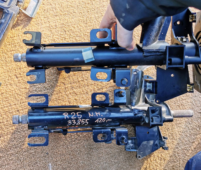
So, column off, let's take a look at things.
New next to old. Aside from some slightly more flexible looking mounting holes (the donor is off an earlier car), they look to be identical.
This is good, as the replacement was specifically listed as for LHD cars (I've not been able to locate a RHD one listed anywhere since I got the car).
While the sheet metal I'd seen bent in the car wasn't massively substantial (and I was able to more or less bend it back into shape with my much abused Saab toolkit pliers), the column itself is quite beefy. Nevertheless, it's taken a heck of a beating.
Looking up the column from the base makes the scale of the damage really obvious.
The top of those brackets should be level. You can see how the shaft itself is pushed off towards frame right as well rather than sitting centrally in the bearing.
Yep, the only place this is going now is into the scrap metal bin.
The metalwork under the dash has been more or less bent back into shape. It's never going to be perfect, but it's a lot better than it was.
To really do any more with that would require at least the instrument panel to come out so I could access things properly from above.
[] Reassembly is as the Haynes manual loves to say, reverse of disassembly.
Only thing I'll say though is to reattach the lower column pinch bolt before anything else. As you need to get things lined up right, laterally and obviously you can't really move things once the column is bolted in.
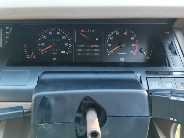
With everything bolted/screwed back together (with the notable exception of the steering wheel) this was the result.
First thing that's obvious is that the ignition barrel is actually in the cutout in the cowl, whereas it used to be displaced about an inch forward and down.
It is still clocked very slightly anticlockwise, but only a tiny bit.
"Before" photo for reference.
At that point it should have been a simple matter to swap the wheel over, I just needed to grab a set of circlip pliers. As I was passing by Halfords while running other errands in the afternoon I thought I'd grab some there. This turned out to be a mistake...the only ones they had were cheap and nasty in the extreme. I wasn't exactly filled with confidence by the packaging!
Yes, that is a Halfords tag stapled to a nameless OEM card package...and the tool in it broke the first time I tried to use it. This was extremely frustrating and meant I wasn't able to get everything back together the same afternoon.
The following morning, armed with a set of actually working set of circlip pliers picked up from Toolstation - which were cheaper than the ones from Halfords - we got the clip off and the wheel transferred over.
Doesn't that look better?
Notable from the driver's seat is that I can actually see the switches and associated indicator lights to the right of the steering wheel now. These were always obscured by the wiper stalk before.
Getting the wheel actually straight was a right faff. It's still clocked very slightly off centre, but I can tweak that when it's convincingly above freezing.
How badly bent was the actual steering shaft? Well about this badly.
That was recorded in landscape...thanks for ignoring the metadata, YouTube.
I don't want to know how much force that took...well actually that's a complete lie. The engineer in me is really curious to know how much force that took.
Here's the state of the keyway the steering lock locates in.
Having the steering wheel actually rotate around its own centre and only moving in one plane rather than two really does make driving the car rather more pleasant.
Here's how the wheel used to move around before:
Have to admit, I was kind of dreading this job. These cars seem to have a bit of a reputation for being difficult to work on, but this job at least really couldn't have been easier. The only holdups were caused by either errors in sequencing on my part or not having tools on hand. I reckon you could definitely easily do this in an hour if you were organised.
That puller built into the steering wheel boss in particular was a really nice thing to find. There were a dozen things which could have made this job a whole lot more annoying like wiring routing and hiding fasteners where other things were in the way, but a lot of that seemed to have been done in a way that recognised that things might need to come back apart one day. The whole job involved probably less than half a dozen different fasteners, including the screws holding the trim panel and cowling on. Think two sizes of Torx bit, an appropriate driver, circlip pliers and a pair of 13mm sockets were the only tools needed.
I'm very glad to have this task ticked off as aside from the steering wheel being wobbly being really annoying, I was never going to fully trust that the wheel wasn't going to snap off in my hands one day due to the trauma the steering shaft had been subject to. Essential? Probably not as it would likely have been fine. Am I glad to have done it anyway? Absolutely.
Current fleet:
07 Volvo V70 SE D5, 88 Renault 25 Monaco, 85 Sinclair C5, 84 Trabant 601S, 75 Rover 3500, 73 AC Model 70.
Today's first patient of the day on the dining...I mean operating table was a Toshiba T3200. This was generally in working order but had an issue whereby the display would start to fade out after 10 or 20 minutes.
Toshibas of this era are pretty much guaranteed to have issues with leaky electrolytic capacitors (whether electrically, physically or both), so I had bought the capacitors to replace the whole lot in the machine. I will tackle the power supply at some point as a precaution, though it actually looked fine - and likely is as it's not actually made by Toshiba so uses completely different capacitors.
The most obvious target though as a likely simpler fix for the actual issue we had was this.
This is the display driver board. The behaviour we had been seeing suggested to me that it was the high voltage (around 500V) supply to the display panel that was failing, and that is derived locally on that little board that lives on the back of the display rather than in the main system power supply.
It's also an easy target and only has five caps on it. Two of which in closer inspection were showing signs of leakage.
The five capacitors were promptly evicted and replaced.
Not my tidiest work, especially as I managed to order radial rather than axial capacitors. Though thankfully the leads were long enough to make it work.
I then put everything back together and set it running a burn-in test through CheckIT for an hour or so as a stress test.
It remained stable without any signs of the display fading, so the fault looks to be repaired.
A little later in the day I returned to the task and went after the T5200 which has recently developed exactly the same problem. This is a little easier as the T5200 has been designed to allow the display to be replaced without having to dismantle the machine. Two screws and it just unclips from the top of the unit.
The HT supply in this case lives in that little box attached to the base of the display. Which after a little head scratching on how to gain access I soon got into.
Nothing too complicated. A lot easier than having to pull the entire monitor to bits.
I had to do a bit of digging then to see if I had the necessary capacitors in stock...at which point I ran into a critical patience failure with my complete lack of an organisation system for storage of electrolytic caps. A single drawer worked when I had a handful - about 25 years ago.
These days, not so much. Cue about an hour and a half of digging through the component trays, boxes around the desk, where they had rolled under my keyboard etc, and organising them each into a labelled bag. Said bags were then arranged in order of capacitance (and voltage rating) in their own box.
I just need to get some more component trays, but this should help my sanity in the short term and meant that checking if I had what I needed took me about 2 minutes rather than half an hour.
Of course did I have the right caps for the second machine? Nope! So that's another order on the way to CPC. Before sending that though I did check to see what the PSU for the Apple II will need and included that in the same order.
The Apple II is up and running and seems to work well with the Floppy Emu disc emulator.
However after about ten minutes the system reverts to a condition whereby it is about as stable as a bottle of nitroglycerin in a microwave. So I think a recap of the power supply secondary is in order.
While I had been looking at the T5200, I'd left the T3200 whirring away to itself (running the old Windows 1.01 promotional demo to keep a moving image on screen), and after pretty much the whole evening it was still running happily.
So that seems to have fixed it. I will still likely look to go through the main power supply at some point - but not right now.
Speaking of power supplies...what about that Toshiba T1600?
First up...it meant I could finally put together this lineup.
T1000, T1200 and T1600.
T1000.
This is the baby of the range, running a 4.77MHz 8088, 512K of memory, a double density floppy drive, and a 256K ROM drive with DOS on it to make life a bit easier. This one sadly is missing some components so is a static exhibit for now.
T1200.
A regularly used machine. 80C86, 1Mb of memory, 20Mb hard drive, 720k floppy and a halfway decent backlit display (which the T1000 lacks).
T1600.
Based around a 12MHz 80C286, 1Mb of memory, EGA graphics (displayed in grey scale obviously), a 20 or 40Mb hard drive, and a 1.44Mb floppy drive.
Cosmetically this one is in decent shape, with very little yellowing. However opening it up immediately found evidence of the usual issues...
The power supply board in this one is in a sorry state...
Especially looking closer.
There are clearly traces which have basically just disappeared. Also a surface mount capacitor on the back of the board has clearly been cooked.
However I don't think it's necessarily a total loss. None of the silicon has - at least visibly - let the magic smoke out. So I'm inclined to take a look at the other two boards I have and replace the cooked transistors on the best looking one with those from this board (and recap it obviously!) and see what happens. Not really anything to lose by trying. Even if it nuked the motherboard, at this point I have two spares! Several of them annoyingly only have Toshiba part numbers on which the internet finds zero matches for so I can't just buy replacements off the shelf.
Current fleet:
07 Volvo V70 SE D5, 88 Renault 25 Monaco, 85 Sinclair C5, 84 Trabant 601S, 75 Rover 3500, 73 AC Model 70.
Zel - a thought has occurred to me. Are you displaying calculators as well as home computers at the show? If so I could lend you my Sinclair Cambridge programmable with the manual set if you haven't managed to find one yet. If so and you can make lunch next Tuesday, Link here, let me know and I'll bring them along.
I used to be indecisive, now I'm not so sure!
I used to ride on two wheels, but now I need all four!