On to the lever assemblies. Again, it's important to realise that a lot of these parts are "adjustable" and in order to replace them exactly how they come off mark them, make notes and diagrams or take photos.
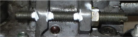
In the case of the accelerator cable lever, the shaft is splined and has a slot cut in the top used as a reference mark. As per Jim's guide, scribe or mark the lever. Getting this wrong on re-assembly can lead to engine runaway or not even starting/idling. I used white paint and a sharp blade. The nut's a 10mm and has a washer behind it - don't lose this.
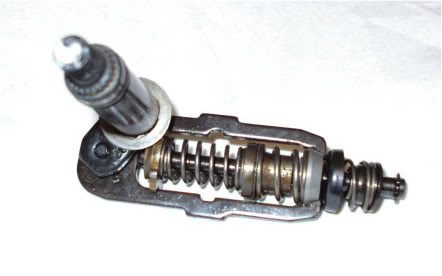
Once marked, I released the spring tension and lifted the complete assembly, tying them together so they stay in order.
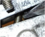
Repeat this process for the fuel cut-out and fast idle (8mm nut) lever or whatever your pump has as they can vary in configuration. Interestingly, when I removed the fuel cut-out nut, washer, lever and spring I noticed the seal was wet and obviously weeping.
Bosch Diesel Injection Pump Disassembly
Moderators: RichardW, myglaren
-
- Posts: 4809
- Joined: 11 Jun 2007, 16:17
- x 232
-
- Posts: 4809
- Joined: 11 Jun 2007, 16:17
- x 232
If you can work around them (unlikely) I recommend leaving these adjustable stops so as not to lose their preset positions.
Using white paint again the position of these stop screws are marked and for added confidence I measured the protruding length from the pump body. I will also count the number of turns to withdrawal.
Max RPM stop A closer view
Anti-stall stop, Full-load screw bottom left and Governor shaft screw
Any remaining stop/set screws I have aren't worth removing though again, due to differing configurations, your pump may differ. Just make sure you can set the removed items back as they were.
-
- Posts: 4809
- Joined: 11 Jun 2007, 16:17
- x 232
With all obstructions clear we can now undo the four allen bolts holding the governor cover to the pump body. Here, it's important to be aware that the two parts are internally connected by the accelerator lever shaft and the cold-start fast-idle shaft via their respective springs. We must detach said springs before fully removing the cover or risk damaging something. By raising the cover slightly, we can see the small fast-idle shaft spring through the gap and easily unhook it with small long-nose pliers. (At this point, my spring decided to detach from the other end and took a dive into the inner workings of the pump body No problem, so don't worry if this happens to you as it can easily be fished out later. Just don't forget or be tempted to rotate the pump shaft).
This isn't the best illustration as it looks like I'm risking marking the mating surfaces of the two halfs while barely having enough gap to work with but that's not the case. I rested the top on the pliers to hold it just high enough to show the spring. It can be raised double that height, maybe more without risk.
The inside of the top showing the fast-idle shaft top right with small spring attached
Once that little spring is free and before the governor cover can be lifted off there are two options for releasing the governor spring. Either raise the opposite end end to see and unhook the governor spring from the governor levers by rotating the governor spring shaft so the flats slide out or, we can do as I did. Push the shaft from the outside through it's bushing as the top is raised. This second option will simply leave the governor spring still attached to the pump where it can easily be disconnected.
The governor spring cage with attached splined shaft
More on this later 8)
-
- Posts: 4809
- Joined: 11 Jun 2007, 16:17
- x 232
With the lid off, we're now ready to being removing the pump inner workings, starting at the governor assemblies in upper part of the pump. As per the previous adjuster screws/stops, mark the governor shaft in relation to the pump body and/or count the number of turns out (once the 14mm locknut is loosened). I would advise only removing the shaft as far as is required to lift off the governor gearwheel and flyweight body otherwise the washer might drop into the pump - again, it's not really a problem as it can be retrieved later.
The next job is to remove the governor lever assembly but I think it might be better to relieve some of the tension on them first and that is done at the distributor head end. First off are the delivery valves, though the head can be removed with them in-situ but I need to see inside them. Be aware they contains several loose parts including shims
-
- Posts: 4809
- Joined: 11 Jun 2007, 16:17
- x 232
Now for the distributor head. This is a little bit tricky but if you're careful and mindful there won't be any problems. What you need to be mindful of is the fact this head is under tension from four springs - two quite powerful so you need to undo the head evenly like a cylinder head so it slides out straight. There's no risk of damage but there is a risk of bits dropping all over the floor. As such, I angled the pump so the head was slightly inclined but I think it's best fully vertical.
If we recall at the beginning I had to remove three black head bolts one at a time and then replace them. Here I'm going to remove two of them fully, leaving the still tight sliver one and the diagonally opposite silver bolt. Only two are required to keep the head true under tension. Don't leave the shim behind...
As it happens, if you do remove this vertically, I'd expect most of it (springs and plunger etc) will stay in the pump. If so, just lift and remove, noting the order and position.
-
- A very naughty boy
- Posts: 49674
- Joined: 30 Apr 2005, 23:33
- x 6214
This is looking really good Mike! Very much the definitive guide
Yes, I would recommend doing the distributor head vertically. I made up a jig to hold the pump in my big vice for this. All it is is a bar with a couple of holes drilled to enable the bar to be bolted to the tow tapped holes on the underside of the pump body.
To ensure all the springs do sit correctly it is essential to reassemble vertically. There is also no worries in using a little grease to "stick" the springs to keep them in place when reassembling; in fact you'll find Bosch do just that...
Jim
Runner, cyclist, time triallist, duathlete, Citroen AX fan and the CCC Citroenian 'From A to Z' Columnist...
-
- Posts: 4809
- Joined: 11 Jun 2007, 16:17
- x 232
-
- Posts: 4809
- Joined: 11 Jun 2007, 16:17
- x 232
-
- A very naughty boy
- Posts: 49674
- Joined: 30 Apr 2005, 23:33
- x 6214
Yes, absolutely correct Mike, three. I only used two to jig it.
Absolutely, they're a piece of engineering to be marvelled at and would make a brilliant ornament, all polished up Perhaps do a nice cutaway one and paint all the cut edges red...MikeT wrote: I wondered what they're for, could mount one as an ornament?
Jim
Runner, cyclist, time triallist, duathlete, Citroen AX fan and the CCC Citroenian 'From A to Z' Columnist...
-
- Posts: 4809
- Joined: 11 Jun 2007, 16:17
- x 232
Where did you get the Bosch method info from Jim? I'm hungry for more...CitroJim wrote:...There is also no worries in using a little grease to "stick" the springs to keep them in place when reassembling; in fact you'll find Bosch do just that...
I'm not too sure on the wisdom of using grease thinking about it, though Bosch are the experts! One of the small springs I pulled from the head still had a lump of grease on the head end - what if it got washed free and covered a low-pressure port or similar? Hopefully it'll get flushed out but even still - grease in the fuel? Much better to use a solid lube that will dissolve in the fuel and a nice little bonus if it had a high cetane rating
Last edited by MikeT on 30 Oct 2009, 18:13, edited 1 time in total.
-
- Donor 2024
- Posts: 2507
- Joined: 17 Jan 2006, 21:22
- x 132
Mike ,
PM sent I hope this is some use to you,
Kenny
PM sent I hope this is some use to you,
Kenny
C5 x7 2.0 HDi 160 hp Estate exclusive, the newbie
Xantia 2.0 Hdi 90hp 1999 only 189,000 and rising!!!!!!! Moved on to a new home
C3 1.4 petrol (SWMBO)
Xantia TD 1.9 Mk 2 Estate LX 1998 model over 210,000 miles now and still rising!!!!!!!!!!!!! now deceased 17/12/2010.
Xantia 2.0 Hdi 90hp 1999 only 189,000 and rising!!!!!!! Moved on to a new home
C3 1.4 petrol (SWMBO)
Xantia TD 1.9 Mk 2 Estate LX 1998 model over 210,000 miles now and still rising!!!!!!!!!!!!! now deceased 17/12/2010.
-
- A very naughty boy
- Posts: 49674
- Joined: 30 Apr 2005, 23:33
- x 6214
Same place as you Mike, by stripping a number of pumps (Lucas as well) and observingMikeT wrote: Where did you get the Bosch method info from Jim? I'm hungry for more...
The grease cannot hurt as long as it's petroleum based. I use my old favourite, Vaseline. It will dissolve quite happily although I have no idea of it's cetane rating...
What is amazing is how the original Bosch grease stays put. Looking at it, I reckon it's similar to Shell Retinax G, a very sticky grease once used in teleprinters.. That stuck like the old proverbial and remained so
This is one place I'd not recommend using a water soluble grease
Jim
Runner, cyclist, time triallist, duathlete, Citroen AX fan and the CCC Citroenian 'From A to Z' Columnist...
-
- Donor 2024
- Posts: 2507
- Joined: 17 Jan 2006, 21:22
- x 132
To Mike and Jim,
Has anyone posted photo's and added info re removing the armour from the Bosch VP20 ac3 pump i have on my car.
If not I'll try and show my endeavours
Kenny
Has anyone posted photo's and added info re removing the armour from the Bosch VP20 ac3 pump i have on my car.
If not I'll try and show my endeavours
Kenny
C5 x7 2.0 HDi 160 hp Estate exclusive, the newbie
Xantia 2.0 Hdi 90hp 1999 only 189,000 and rising!!!!!!! Moved on to a new home
C3 1.4 petrol (SWMBO)
Xantia TD 1.9 Mk 2 Estate LX 1998 model over 210,000 miles now and still rising!!!!!!!!!!!!! now deceased 17/12/2010.
Xantia 2.0 Hdi 90hp 1999 only 189,000 and rising!!!!!!! Moved on to a new home
C3 1.4 petrol (SWMBO)
Xantia TD 1.9 Mk 2 Estate LX 1998 model over 210,000 miles now and still rising!!!!!!!!!!!!! now deceased 17/12/2010.
-
- Posts: 4809
- Joined: 11 Jun 2007, 16:17
- x 232
If the parts haven't fallen off, simply take them apart. I prefer to keep them in order for now but will be seperating each part for later cleaning. This how the parts are ordered on the plunger shaft and distributor head
So with the distributor head and springs now removed, we can take out the governor lever assembly by loosening/removing the two pivot bolts either side of the pump with a 14mm socket
-
- Posts: 4809
- Joined: 11 Jun 2007, 16:17
- x 232