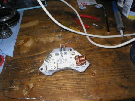

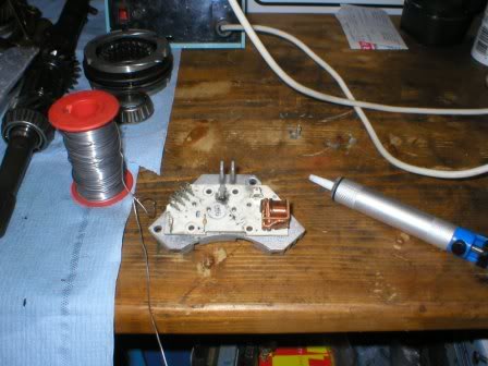
Here is how to do the job:
1. Clamp the module into a vice and using a 6.5mm drill in a hand drill, drill out the rivets holding the transistors.
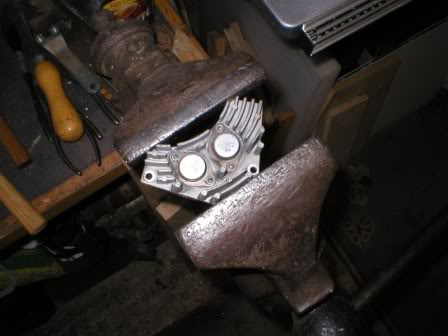
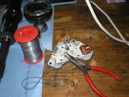
2. Drift out the old rivets carefully.
3. Desolder the base and emitter pins using a good solder sucker until the eyelets look clear of solder.
4. Using a pair of needle-nosed pliers, wiggle the pins to break any last solder still holding the pins to the eyelets. The transistors will soon start to wobble, showing they're ready to come out.
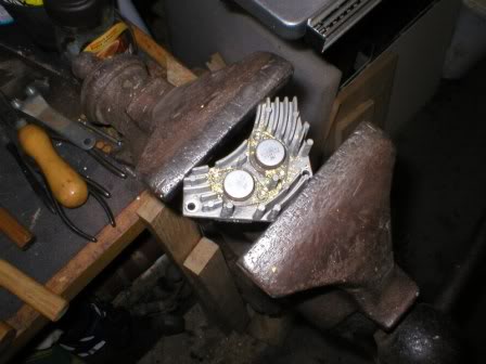
5. Remove the transistors. Carefully lever up the board adjacent to where it is held on little pillars near the edges. This is an interference fit so be careful.
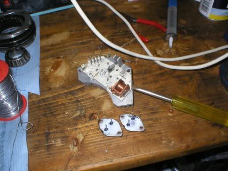
6. Lift the board up and away, being very careful not to disturb the annular resistor shown at the tip of the screwdriver.
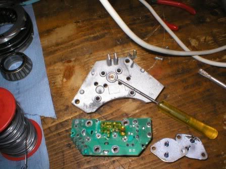
7. Give the board a clean using a gentle solvent (Electrolube ULS or similar), paying attention to the solder pads that connect to the transistor collectors and bear on the pillars through which the transistor fixing rivets pass through. Clean the pillars on the heatsink. Replace the board on the heatsink.
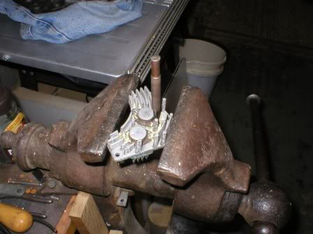
8. Smear just enough heatsink compound onto the new transistors to apply a thin even film all over. Don't use too much! Insert the transistors. I used a bit too much here
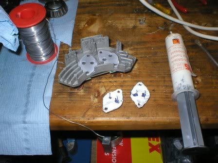
9. Replace the rivets with M3.5 bolts and nuts trimmed off to be just long enough. Use pan-head bolts and place the heads on the circuit board side. Tighten moderately to ensure a good collector connection as this is formed through the heatsink pillars and the pads on the underside of the board.
10. Solder the new transistors in. This must be done after tightening the screws to avoid setting up any stresses. Don't use too much solder as it may run down the emitter and base pins and a blob may cause a short against the heatsink. Make sure these joints are good as 10A or so can flow down the emitter pin.
11. Job done!