Hi all.....
Got an issue I can’t get to the bottom of, of anyone can offer and advice, information or opinions I’d be very grateful.
The issue is, the rear suspension is far too hard, as if the back is stuck in sports mode.
I’ve been through a few things recently and with the help of a mechanic friend I think I’ve narrowed it down to possibly having not enough voltage to a solenoid on the rear accumulator valve block. Just today we had the block apart expecting to find a sticky valve or something similar. All the valves and solenoid seem free to move so we went on to check the solenoid. With a 12v feed the solenoid does move, I’m not totally sure if it moves enough but it definitely moves. We went on to check the electric feed to the solenoid. With the car running and me hitting the sports switch on and off the feed fluctuated from 0v to 8v. So..... I’m now wondering if it should be 12v and I’ve got an electric issue somewhere. Or...... possibly 8v is correct and my issue is the solenoid not working correctly.
Any information at all on this would be greatly received.
Also if anyone could point me in the direction of a wiring diagram I’d also appreciate that.
Thanks all
C5 hydractive 3 electrical issue
Moderator: RichardW
-
GiveMeABreak

- Forum Admin Team
- Posts: 37456
- Joined: 15 Sep 2015, 19:38
- Location: West Wales
- My Cars: C3 Aircross SUV HDi Flair Peperoncino Red (The Chili Hornet)
C5 X7 2.0 HDi Exclusive Mativoire Beige (The Golden Hornet)
C3 1.6 HDi Exclusive Aluminium Grey (The Silver Hornet)
C5 MK II 2.0 HDi Exclusive Obsidian Black
C5 MK I 2.0 HDi SX Wicked Red
Xantia S2 2.0 HDi SX Hermes Red
C15 Romahome White
XM 2.0 Turbo Prestige Emerald Green Pearlescent
XM 2.0 Turbo Prestige Polar White
XM 2.0 SX Polar White
CX 20 Polar White
GS 1220 Geranium Red
CX 2.4 Prestige C-Matic Nevada Beige
GS 1000 Cedreat Yellow - x 5743
Re: C5 hydractive 3 electrical issue
Have you considered you may need your corner spheres or the rear centre spheres replacing....
Please Don't PM Me For Technical Help
Marc
Marc
-
Dunkah
- Donor 2023
- Posts: 87
- Joined: 17 Jan 2021, 14:41
- Location: Hampshire
- Lexia Available: Yes
- My Cars: C4 e-hdi
C5 2008 tourer hdi exclusive
Xantia 2000 mk11 hdi exclusive (sold but still going)
1979 mini clubman
1972 vw microbus
1970 vw beetle
Model A rat rod - x 8
Re: C5 hydractive 3 electrical issue
Hi Marc, yeah that was my first consideration. The centre spheres are the ones responsible for stiffness, (please correct me if I’m wrong) so I did those, absolutely no difference at all. Whilst doing that I discovered that the reservoir tank had a split in it, so I thought possibly that had something to do with it, replaced it and again, absolutely no difference. I do have a pair of corner spheres which I was intending to do but it seems to be nearly impossible to get to them with enough room to get any tools onto them to get the old ones off.
-
GiveMeABreak
- Forum Admin Team
- Posts: 37456
- Joined: 15 Sep 2015, 19:38
- Location: West Wales
- My Cars: C3 Aircross SUV HDi Flair Peperoncino Red (The Chili Hornet)
C5 X7 2.0 HDi Exclusive Mativoire Beige (The Golden Hornet)
C3 1.6 HDi Exclusive Aluminium Grey (The Silver Hornet)
C5 MK II 2.0 HDi Exclusive Obsidian Black
C5 MK I 2.0 HDi SX Wicked Red
Xantia S2 2.0 HDi SX Hermes Red
C15 Romahome White
XM 2.0 Turbo Prestige Emerald Green Pearlescent
XM 2.0 Turbo Prestige Polar White
XM 2.0 SX Polar White
CX 20 Polar White
GS 1220 Geranium Red
CX 2.4 Prestige C-Matic Nevada Beige
GS 1000 Cedreat Yellow - x 5743
Re: C5 hydractive 3 electrical issue
Yes in normal suspension mode often referred to as 'Comfort' mode, all 7 spheres (the 4 corners and the 1 front and 2 rear central spheres) are in operation. When sport mode is active, the 3 centre spheres are cut out to provide a firmer ride and stiffer cornering.
Regarding the split in the tank - have a read of my post here for some advisory warnings and some labels:
LDS Tank Bursting Warning Labels
Regarding the split in the tank - have a read of my post here for some advisory warnings and some labels:
LDS Tank Bursting Warning Labels
Please Don't PM Me For Technical Help
Marc
Marc
-
white exec

- Moderating Team
- Posts: 7445
- Joined: 21 Dec 2015, 12:46
- Location: Sayalonga, Malaga, Spain
- My Cars: 1996 XM 2.5TD Exclusive hatch RHD
1992 BX19D Millesime hatch LHD
previously 1989 BX19RD, 1998 ZX 1.9D auto, 2001 Xantia 1.8i auto
and lots of Rovers before that: 1935 Ten, 1947 Sixteen, 1960 P5 3-litre, 1966 P6 2000, 1972 P6 2000TC, and 1975 P6B 3500S - x 1752
Re: C5 hydractive 3 electrical issue
For Hydractive 2 (the predecessor to your H3), the solenoids (electrovalves) receive a 12v supply from the suspension ECU for just 0.5 sec (solenoid pull-in) immediately followed by a continuous 25% duty cycle PWM (a 12v square wave, which when meter-reads as approximately 3v) as solenoid hold-in. This arrangement limits power consumption of the solenoids, and reduces heating of them. NB: They must NOT be fed with continuous 12v, even for test purposes.
Current draw for pull-in is approximately 3A; d.c. resistance of the EV is around 4.5 ohm.
The H2 electrovalves also incorporate a reverse diode, encapsulated in the coil winding. This is there to ensure proper PWM operation, and to protect the ECU from a reverse voltage spike when the EV switches off.
If one of these diodes gives up (not unknown) the EV will not hold in properly, which would leave the suspension in Firm mode. As an insurance measure, it is possible to add an extra diode for each EV externally, either at the EV, or (often more conveniently) at the cable leaving the suspension ECU. The diode should be decently rated, eg 400v 6A to ensure long life. It should also be 'reverse' connected, i.e. diode stripe/band to the +ve supply cable, other end to a good Ground.
Everything above relates to H2. Others here might point up differences with H3, but the systems are very similar.
Chris
-
Dunkah
- Donor 2023
- Posts: 87
- Joined: 17 Jan 2021, 14:41
- Location: Hampshire
- Lexia Available: Yes
- My Cars: C4 e-hdi
C5 2008 tourer hdi exclusive
Xantia 2000 mk11 hdi exclusive (sold but still going)
1979 mini clubman
1972 vw microbus
1970 vw beetle
Model A rat rod - x 8
Re: C5 hydractive 3 electrical issue
Thanks Marc, think I’ve already seen that post a while ago. I do have a brand new tank ready to fit but I want to get my current situation resolved before I fit itGiveMeABreak wrote: ↑23 Aug 2021, 16:20 Yes in normal suspension mode often referred to as 'Comfort' mode, all 7 spheres (the 4 corners and the 1 front and 2 rear central spheres) are in operation. When sport mode is active, the 3 centre spheres are cut out to provide a firmer ride and stiffer cornering.
Regarding the split in the tank - have a read of my post here for some advisory warnings and some labels:
LDS Tank Bursting Warning Labels
-
Dunkah
- Donor 2023
- Posts: 87
- Joined: 17 Jan 2021, 14:41
- Location: Hampshire
- Lexia Available: Yes
- My Cars: C4 e-hdi
C5 2008 tourer hdi exclusive
Xantia 2000 mk11 hdi exclusive (sold but still going)
1979 mini clubman
1972 vw microbus
1970 vw beetle
Model A rat rod - x 8
Re: C5 hydractive 3 electrical issue
Thanks Chris, very useful info.white exec wrote: ↑23 Aug 2021, 17:46 For Hydractive 2 (the predecessor to your H3), the solenoids (electrovalves) receive a 12v supply from the suspension ECU for just 0.5 sec (solenoid pull-in) immediately followed by a continuous 25% duty cycle PWM (a 12v square wave, which when meter-reads as approximately 3v) as solenoid hold-in. This arrangement limits power consumption of the solenoids, and reduces heating of them. NB: They must NOT be fed with continuous 12v, even for test purposes.
Current draw for pull-in is approximately 3A; d.c. resistance of the EV is around 4.5 ohm.
The H2 electrovalves also incorporate a reverse diode, encapsulated in the coil winding. This is there to ensure proper PWM operation, and to protect the ECU from a reverse voltage spike when the EV switches off.
If one of these diodes gives up (not unknown) the EV will not hold in properly, which would leave the suspension in Firm mode. As an insurance measure, it is possible to add an extra diode for each EV externally, either at the EV, or (often more conveniently) at the cable leaving the suspension ECU. The diode should be decently rated, eg 400v 6A to ensure long life. It should also be 'reverse' connected, i.e. diode stripe/band to the +ve supply cable, other end to a good Ground.
Everything above relates to H2. Others here might point up differences with H3, but the systems are very similar.
Don’t suppose you can shed any light on where the diode concerned might be located? Or how to test it?
Thanks
-
white exec
- Moderating Team
- Posts: 7445
- Joined: 21 Dec 2015, 12:46
- Location: Sayalonga, Malaga, Spain
- My Cars: 1996 XM 2.5TD Exclusive hatch RHD
1992 BX19D Millesime hatch LHD
previously 1989 BX19RD, 1998 ZX 1.9D auto, 2001 Xantia 1.8i auto
and lots of Rovers before that: 1935 Ten, 1947 Sixteen, 1960 P5 3-litre, 1966 P6 2000, 1972 P6 2000TC, and 1975 P6B 3500S - x 1752
Re: C5 hydractive 3 electrical issue
Testing the diode (buried in the sealed EV coil windings) is not a straightforward matter, although Simon (Mandrake) here has written up a procedure for it.
Probably best to check that the diode isn't shorted (unlikely, they usually blow open) by simply checking that the EV clicks when closing and opening.
Given that, just add an external one (to be sure it has a working one), and go from there.
You can also wire in (to the same point tap-in point as the diode) an LED, in series with a 120R resistor connected to Gnd.
The LED will show when the EV is energised (in Soft mode), but coming on brightly for the 0.5sec pull-in, and then dropping back in brightness for the hold-in. By having such LEDs (one for each EV) you can also monitor the action of all the sensors that feed into the Hydractive system: throttle action, steering movement, body movement, etc. The two LEDs can either be dash-fitted, or located somewhere temporary, if just for a brief test. If dash mounted, they can be switched off by a simple switch in the LED ground connection.
Chris
-
Dunkah
- Donor 2023
- Posts: 87
- Joined: 17 Jan 2021, 14:41
- Location: Hampshire
- Lexia Available: Yes
- My Cars: C4 e-hdi
C5 2008 tourer hdi exclusive
Xantia 2000 mk11 hdi exclusive (sold but still going)
1979 mini clubman
1972 vw microbus
1970 vw beetle
Model A rat rod - x 8
Re: C5 hydractive 3 electrical issue
Excellent, I’ll look into that.white exec wrote: ↑23 Aug 2021, 18:59 Testing the diode (buried in the sealed EV coil windings) is not a straightforward matter, although Simon (Mandrake) here has written up a procedure for it.
Probably best to check that the diode isn't shorted (unlikely, they usually blow open) by simply checking that the EV clicks when closing and opening.
Given that, just add an external one (to be sure it has a working one), and go from there.
You can also wire in (to the same point tap-in point as the diode) an LED, in series with a 120R resistor connected to Gnd.
The LED will show when the EV is energised (in Soft mode), but coming on brightly for the 0.5sec pull-in, and then dropping back in brightness for the hold-in. By having such LEDs (one for each EV) you can also monitor the action of all the sensors that feed into the Hydractive system: throttle action, steering movement, body movement, etc. The two LEDs can either be dash-fitted, or located somewhere temporary, if just for a brief test. If dash mounted, they can be switched off by a simple switch in the LED ground connection.

-
myglaren

- Forum Admin Team
- Posts: 25493
- Joined: 02 Mar 2008, 13:30
- Location: Washington
- My Cars: Mazda 6
Ooops.
Previously:
2009 Honda Civic :(
C5, C5, Xantia, BX, GS, Visa.
R4, R11TXE, R14, R30TX - x 4924
Re: C5 hydractive 3 electrical issue
Isn't it this that Brian Pimmer's magic box was supposed to fix?
-
white exec
- Moderating Team
- Posts: 7445
- Joined: 21 Dec 2015, 12:46
- Location: Sayalonga, Malaga, Spain
- My Cars: 1996 XM 2.5TD Exclusive hatch RHD
1992 BX19D Millesime hatch LHD
previously 1989 BX19RD, 1998 ZX 1.9D auto, 2001 Xantia 1.8i auto
and lots of Rovers before that: 1935 Ten, 1947 Sixteen, 1960 P5 3-litre, 1966 P6 2000, 1972 P6 2000TC, and 1975 P6B 3500S - x 1752
Re: C5 hydractive 3 electrical issue
There were a couple of packaged offerings - another from 'e-crofting' iirc.
Basically, these were just a pair of diodes in a small box/casing. No LEDs were included.
Basically, these were just a pair of diodes in a small box/casing. No LEDs were included.
Chris
-
Dunkah
- Donor 2023
- Posts: 87
- Joined: 17 Jan 2021, 14:41
- Location: Hampshire
- Lexia Available: Yes
- My Cars: C4 e-hdi
C5 2008 tourer hdi exclusive
Xantia 2000 mk11 hdi exclusive (sold but still going)
1979 mini clubman
1972 vw microbus
1970 vw beetle
Model A rat rod - x 8
Re: C5 hydractive 3 electrical issue
Interesting.... I’ll look into that. Thankswhite exec wrote: ↑24 Aug 2021, 07:07 There were a couple of packaged offerings - another from 'e-crofting' iirc.
Basically, these were just a pair of diodes in a small box/casing. No LEDs were included.
-
white exec
- Moderating Team
- Posts: 7445
- Joined: 21 Dec 2015, 12:46
- Location: Sayalonga, Malaga, Spain
- My Cars: 1996 XM 2.5TD Exclusive hatch RHD
1992 BX19D Millesime hatch LHD
previously 1989 BX19RD, 1998 ZX 1.9D auto, 2001 Xantia 1.8i auto
and lots of Rovers before that: 1935 Ten, 1947 Sixteen, 1960 P5 3-litre, 1966 P6 2000, 1972 P6 2000TC, and 1975 P6B 3500S - x 1752
Re: C5 hydractive 3 electrical issue
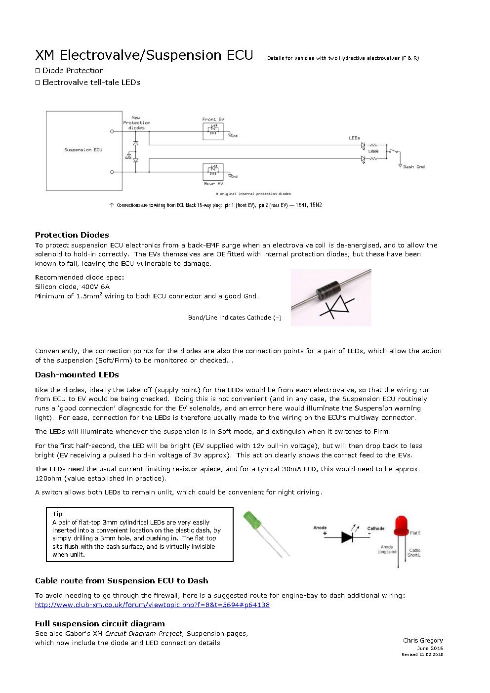
This is an info sheet that I ran out in 2016 (for XM, Hydractive 2), showing connection of the additional protection diodes, and suspension LEDs...
↓ Click to enlarge
↓ Click to enlarge
Chris
-
Dunkah
- Donor 2023
- Posts: 87
- Joined: 17 Jan 2021, 14:41
- Location: Hampshire
- Lexia Available: Yes
- My Cars: C4 e-hdi
C5 2008 tourer hdi exclusive
Xantia 2000 mk11 hdi exclusive (sold but still going)
1979 mini clubman
1972 vw microbus
1970 vw beetle
Model A rat rod - x 8
Re: C5 hydractive 3 electrical issue
Excellent! Thanks for that Chris. Will this still be relevant for hydactive 3?white exec wrote: ↑24 Aug 2021, 09:54 This is an info sheet that I ran out in 2016 (for XM, Hydractive 2), showing connection of the additional protection diodes, and suspension LEDs...
↓ Click to enlarge